Measuring the imaging quality of optics
Optical systems are used in numerous areas of life and must fulfill a specific functionality depending on the application. For example, cameras need to have the highest possible image quality when used in different lighting conditions, but also for security, e.g. in automotive camera systems or surveillance cameras. Regardless of the specific optical application, image quality is the key factor determining the functionality and performance of objective lenses.
Precise determination of image quality is an essential task in the development and quality control of lenses and optical systems. The MTF (modulation transfer function) as the most important measurement parameter in this area is a quantitative measure and objective criterion for the image quality of optics. It is a generally recognized method for determining the image quality of a lens. In addition to MTF, a large number of other optical parameters are measured to characterize optical systems. Furthermore, MTF measurements at finite and infinite object distances are necessary for assessing the image quality.
High measurement accuracy, repeatability and traceability of measurement results to international standards are of particular importance when measuring image quality. In addition, there are new software requirements and extended application possibilities for the measuring systems with regard to the range of measurable test samples.
Things to know about MTF measurement
What ist MTF measurement and what is the prupose of MTF measurement?
The modulation transfer function (MTF) is the generally accepted and fundamental parameter for the characterization of optical systems worldwide. MTF is a quantitative measure as well as an objective criterion for the imaging quality of optics.
For which optics is the MTF measured?
MTF is used for a wide range of optics from simple components such as spherical single lenses to complex lenses. Examples include photolithographic optics, intraocular lenses, endoscopes, riflescopes, telescopes, spotting scopes, binoculars, AR/VR optics, cine lenses, automotive lenses and many others.
The importance of MTF measurement for optics
The MTF is a tool for optical designers to quantify the overall imaging performance of a system in terms of resolution and contrast. Knowledge of the MTF curves of the lenses and camera sensors involved in an optical system is used for optimization of the optical system performance.
Lenses can vary in their imaging quality during production. To meet the often high demands on imaging performance, lenses are characterized and evaluated using MTF as the most important parameter. MTF provides a meaningful quality function for the objective evaluation of optical systems in the optical industry.
When it comes to imaging an object with the desired accuracy, MTF data provide the necessary basis for optical design. Resolution and contrast are of particular importance. MTF data can greatly simplify the selection of the appropriate lens for an application.
Applications
In order to meet the high demands on image quality, objective lenses are characterized and evaluated using the modulation transfer function (MTF) as the most important parameter. TRIOPTICS offers the widest range of products in this area - the ImageMaster® series was specially developed for a wide variety of MTF measurements. As a global standard for testing the imaging quality of objective lenses, e.g. for smartphone and surveillance cameras as well as for camera modules in vehicles, a wide range of measurement parameters leads to high efficiency in research and development as well as in the testing of prototypes and in production.
- ImageMaster® HR 2 – The MTF test station preferred by R&D laboratories worldwide.
- ImageMaster® Universal – MTF measurement in the wide spectral range from UV to the visible spectrum to IR.
- ImageMaster® PRO – Image quality and MTF testing devices for mass production.
- ImageMaster® AR/VR/MR – Test devices for Virtual Reality, Augmented Reality and Mixed Reality optics.
- ImageMaster® HR TempControl – Measurement of image quality in the temperature range from -40 °C to 120 °C.
- ImageMaster® Cine – Testing and fine-tuning of the image quality of high-quality objective lenses from the photo and film industry.
- ImageMaster® ENDO PRO – Test of the image quality of rigid endoscopes.
- ImageMaster® Afocal – Image quality testing of telescopes, riflescopes, binoculars and spotting scopes.
Small and medium-sized lenses
Today, small and medium-sized lenses, e.g. for smartphone, photo and film cameras, offer versatile functionality and high image quality. In safety-critical areas, optical functionality and performance are also required in extreme temperatures or demanding lighting conditions. Added to this is the requirement for precise measurement of test samples with large focal length ranges. The MTF test station ImageMaster® HR 2 can be used to measure visual and infrared lenses. The following parameters can be measured:
- MTF on-axis and off-axis
- Effective Focal Length (EFL)
- Distortion
- Field curvature
- Lateral and longitudinal chromatic aberrations
- Astigmatism
- Chief Ray Angle
- PSF (Point Spread Function)
- Veiling Glare
- Depth of focus
- Field of view
- Flange Focal Length (FFL)
- Relative illumination
All MTF measurements can be performed with the ImageMaster® HR 2 in finite and infinite measurement position.
Measurement in the extended temperature range
In addition to military and aerospace applications, cameras are also among the safety-critical systems in the automotive industry whose properties must be tested and ensured over a wide temperature range. The ImageMaster® HR TempControl enables the image quality to be tested in the extended temperature range from -40 °C to 120 °C. The following parameters are measured:
Measurement parameters:
- Effective Focal Length (EFL)
- Flange Focal Length (FFL)
- MTF vs Frequency
- MTF vs Field
- MTF vs Focus
- MTF vs Focus vs Field
- Field curvature
- Distortion
- Depth of focus
- Chief Ray Angle
Medium and larger lenses in the extended spectral range
For medium-sized and larger lenses, e.g. in camera lens manufacturing and the development of aerial lenses or lenses for space exploration, the highest demands are placed on accuracy in a wide spectral range of MTF measurement from UV to the visible spectrum to IR (NIR/SWIR/MWIR/LWIR). In addition, maximum requirements are placed on the stability of the optical systems used in these areas. The MTF test station ImageMaster® Universal is used to measure lenses and objectives in all spectral ranges from UV to LWIR. The following parameters can be measured:
- MTF on-axis and off-axis
- Effective Focal Length (EFL)
- Distortion
- Field curvature
- Lateral and longitudinal chromatic aberrations
- Astigmatism
- Chief Ray Angle
- PSF (Point Spread Function)
- Depth of focus
- Field of view
- Back focal length (absolute/relative)
- Relative and absolute transmission
- Relative illumination
All MTF measurements can be performed with the ImageMaster® Universal in finite, infinite and afocal measurement position.
Knowledge base
MTF testing (Modulation Transfer Function)
The Modulation Transfer Function (MTF) is an important aid to objective evaluation of the image-forming capability of optical systems. Not only that the MTF provides a means of expressing the imaging quality of optical systems objectively and quantitatively, but it can be calculated from the lens design data. In this way it allows optical and systems designers to predict reliably the performance of the optical systems. The manufacturers can compare the image quality of the manufactured lenses with the design expectations.
Modulation Transfer Function
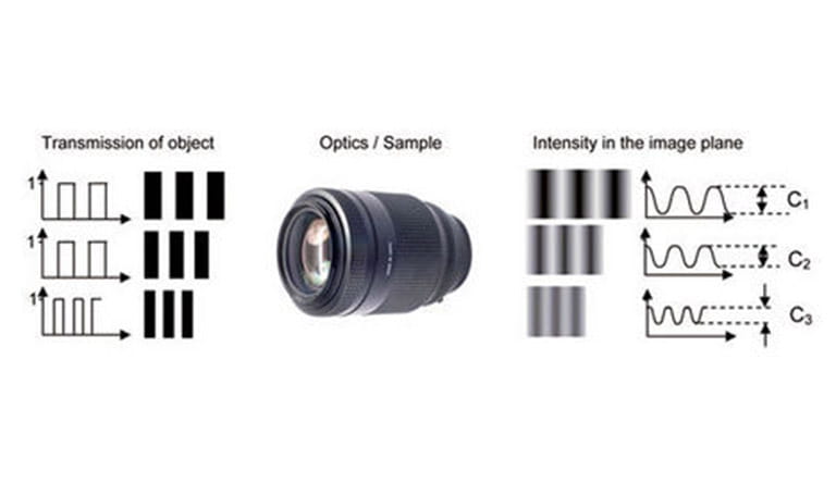
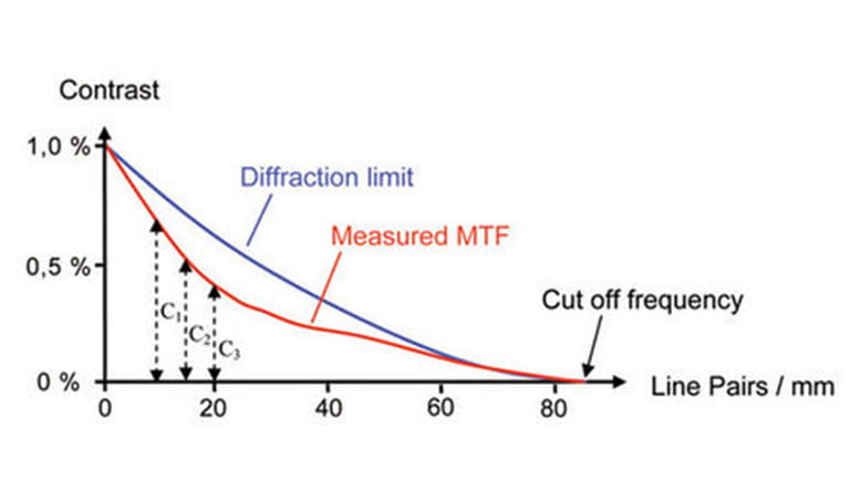
The Modulation Transfer Function (MTF), describing the resolution and performance of an optical system, is the ratio of relative image contrast divided by relative object contrast MTF = Relative Image Contrast/Relative Object Contrast. When an object (illuminated target or reticle) is observed with an optical system, the resulting image will be somewhat degraded due to inevitable aberrations and diffraction phenomena. In addition, a real lens will not fully conform to the design data. Manufacturing errors, assembly and alignment errors in the optics will deteriorate the overall imaging performance of the system.By convention, the modulation transfer function is normalized to unity at zero spatial frequency. For low spatial frequencies, the modulation transfer function is close to 1 (or 100%) and generally falls as the spatial frequency increases until it reaches zero. The contrast values are lower for higher spatial frequencies as shown above. As spatial frequency increases, the MTF curve falls until it reaches zero. This is limit of resolution for a given optical system or the so called cut off frequency (see figure below). When the contrast value reaches zero, the image becomes a uniform shade of grey.
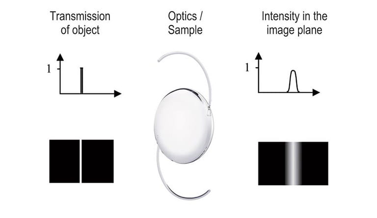
Modern MTF-Testers like the ImageMaster® use a single illuminated slit on opaque background as the object. From a mathematical point of view a single slit can be regarded as the sum over all spatial frequencies (Fourier synthesis). All frequencies contribute with the same amplitude (=1) to this slit not taking the finite slit width into account for this description. This single slit will be imaged into the image plane of the sample. Due to diffraction and aberrations there will be no perfect slit image in this plane, instead the slit image is broadened. It represents the so called Line Spread Function (LSF).
The modulation transfer function varies not only related to the spatial frequency but also with the position in the field of view. The MTF measurement along the axis of symmetry of the optical system is known as on-axis measurement.
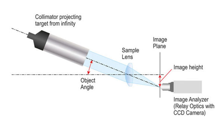
To completely characterize the imaging performance of an optical system, the MTF must be measured at different positions within the field of view. The MTF measurement within the field of view is known as off-axis measurement. In order to achieve an off-axis measurement, the target is moved in the field of view at the desired object position and the image analyzer to the corresponding image position.
The MTF measurement can be accomplished at a single wavelength or in a spectral range covering a finite band of wavelengths. The resulting measurement data are known as monochromatic or polychromatic MTF values, respectively. Usually the MTF is used in its one-dimensional form, calculated for one azimuthal section through the image plane. The azimuth (section plane) of the object pattern is called sagittal azimuth when the prolongation of the slit or object passes through the reference axis. When the prolongation of the slit pattern is perpendicular to the reference axis, the azimuth is called tangential azimuth.
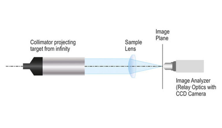
In this so-called finite-finite imaging condition the illuminated slit or crosshair target is directly moved in the object plane of the sample. In the more common infinite-finite imaging condition, the illuminated slit or crosshair is part of a collimator projecting the target to infinity. The collimator is then oriented at different off axis angles for characterizing the MTF at the corresponding image fields.
Our Newsletter – Your advantage in knowledge
Be one of the first to experience our product novelities and innovative application possibilities.


