Testing of camera modules
Camera systems are becoming increasingly complex and must operate with absolute reliability. They are used in safety-critical environments where product failure is simply not an option. Only a full performance test can ensure that all features of the camera module have been tested to meet the demanding requirements.

Automotive
- ADAS (Visible camera, 3D camera, Night vision camera, LiDAR)
- Interior observation, DMS, Head up Displays, Touchless Control
- Mirror replacement

Industrial applications
- Machine vision
- Barcode readers
- Navigation & Geospatial
- Smart farming equipment
- Borescopes

Security, Healthcare & Consumer electronics
- Surveillance
- Medical cameras
- Endoscopes
- Video conferencing
- Sport & entertainment
Knowledge base
- Image quality testing of mass-produced camera modules
- Finite testing
- Testing using collimator domes
- Advantages of testing with collimators
- Additional tests: business as usual
Image quality testing of mass-produced camera modules
Image quality testing of complete cameras and assembled camera modules is done by imaging a suitable target using the camera module under test and evaluating the quality of the reproduction of the target. New approaches for testing methodologies are required to keep up with technological developments and economic pressure. Most of these can also be used in a similar fashion for all other camera testing applications, from high-end scientific to thermal imaging surveillance cameras.
Most consumer-type camera modules are integrated into devices such as smartphones and webcams and use relatively short-focal-length (1 to 5 mm), wide-field-of-view optics and either CCD or CMOS color sensors.
The parameters typically extracted during testing of such a module can broadly be classified into five categories: image quality via the modulation transfer function, the spatial frequency response; properties of the optical system (e.g., distortion, relative illumination); optomechanical properties (e.g., relative alignment of the optics and the sensor or autofocus precision); color properties (e.g., color rendition, white balance); and sensor properties (e.g., dynamic range, linearity, noise, bad pixels). For modules incorporating flash capabilities, the alignment, illumination profile and intensity of the flash unit can be characterized as well. We will focus on the first three topics .
Finite testing
Although most camera modules are designed to be used with the object at a larger distance (infinite conjugate), conventional testing techniques usually place a test target with various patterns – typically a test chart – at a shorter distance (finite conjugate) from the module.
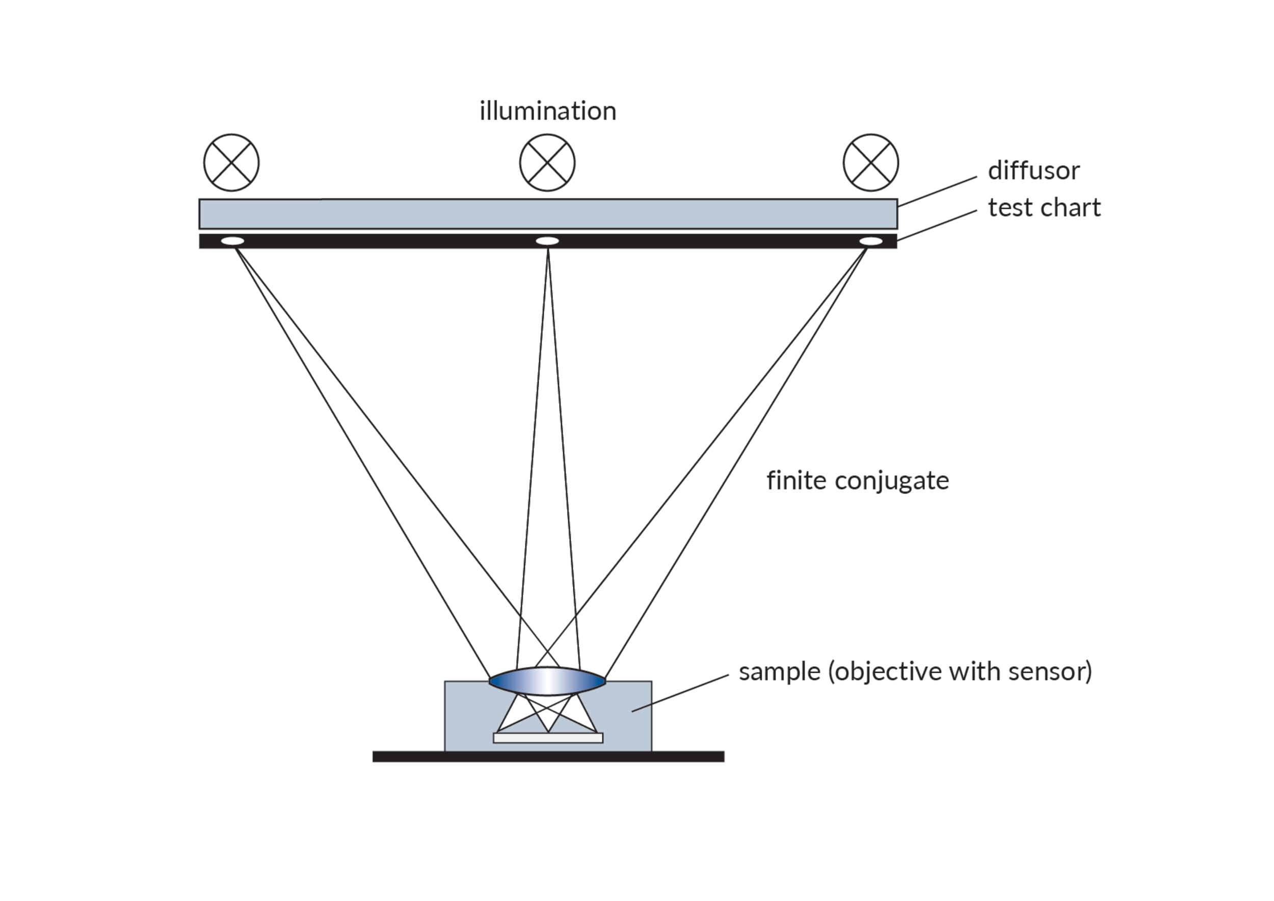
Today, testing with test charts in finite distance is standard, done by image analysis software in real time. Figure 1 shows a schematic representation of a test chart system in finite configuration. The device under test (DUT) is placed in front of an illuminated chart with different markers and patterns on it. An image is then taken with the DUT, and software algorithms analyze the position and shape of the markers, and extract the performance parameters of the camera module.
A modified version of this setup incorporates a relay lens in between sample and chart to create a virtual image of the chart as seen from infinite distance. This approach usually requires a custom, high-quality relay lens, especially for larger-field-of-view applications and broadband (e.g., daylight) illumination, which can make such a setup complex and commercially unviable. This solution should be used only if infinity conjugate measurement and a more complex chart evaluation are required.
This test chart technology is relatively easy to deploy and combines a high density of measurement points with the ability to use different types of markers and patterns on different field positions of a single chart. It is typically used for sensor resolutions of up to 13 MP and testing in finite or close-to-infinite distances. However, because of recent advances in manufacturing technology, this technology reaches its limits as the industry moves to sensor resolutions of 13 MP and higher, which tightens the requirements on optics and the alignment of the individual components of the module.

Figure 1
Common precision and repeatability bottlenecks include the need for high homogeneity of the illumination over a large area, edge contrast and precision of the patterns on the test charts, and the required reproducible spectral distribution lighting, which is usually done with LEDs.
The size of the test instrument is another important factor in a production environment: For the wide-angle, large-field-of-view optics typically found in consumer camera modules, a large test chart is required. The larger the angular field of view, the larger the test chart must be for a given finite object distance, which cannot be set too small for infinity-set fixed-focus objectives. The situation is similar for modules that have a focusing capability – in this case, shorter object distances can be used, but the setup does not properly reflect the final application. For large test charts, the corresponding large instrument requires more precious factory floor space.

Figure 2
Testing using collimator domes
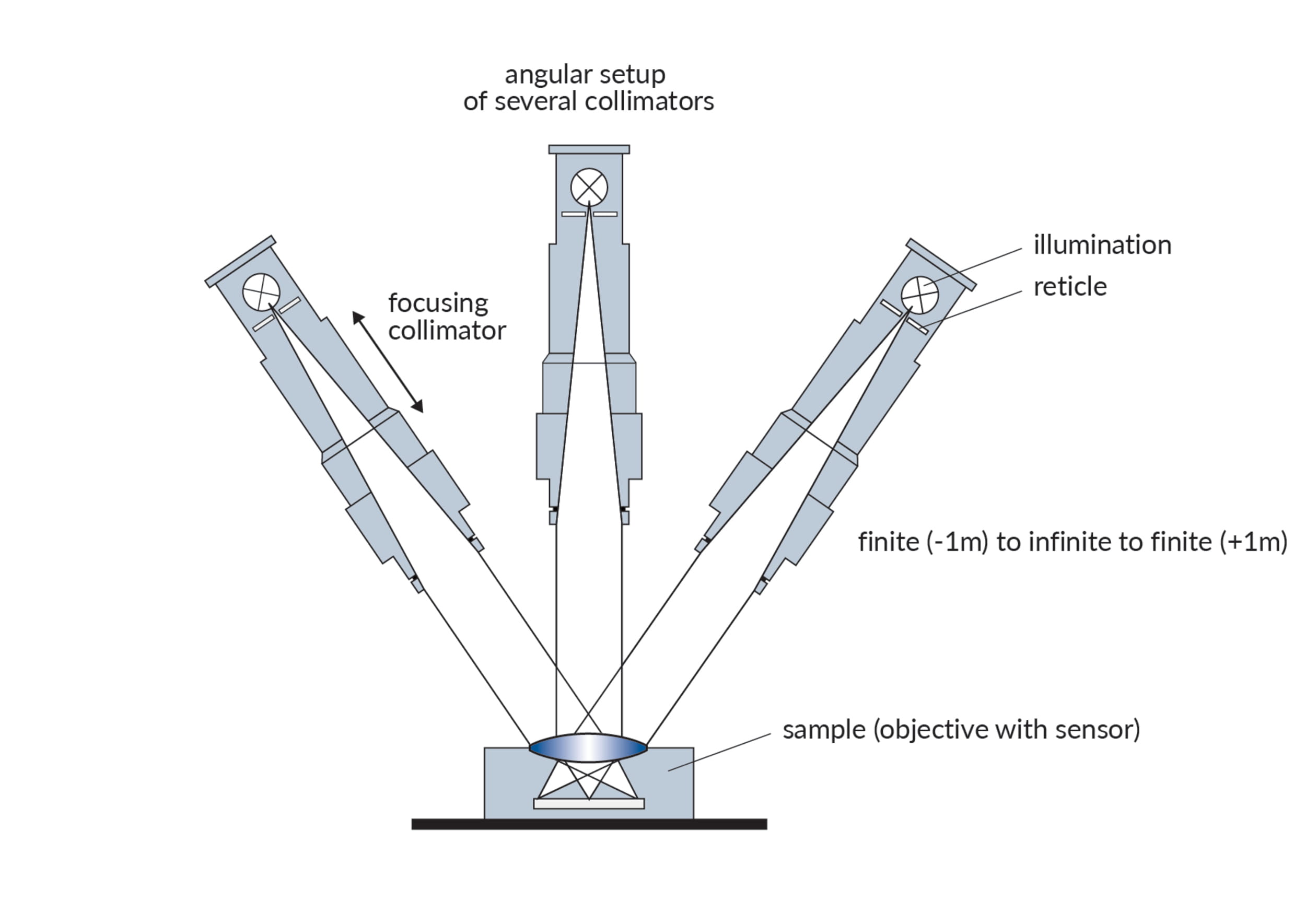
An alternative approach for testing camera modules with larger object distances between about 1 m and infinity is to use a set of collimators as target projectors where each measurement point on the image sensor is provided by a dedicated collimator. A collimator consists of an illuminated target structure (the reticle) in the focal plane of an objective lens. The collimator projects the target virtually onto the DUT (Figure 2). The collimators can be either fixed-focus with preset infinity or finite object distances, or they can be motorized for variable object distances.
The collimators are arranged in space so that the optical axes meet at the entrance pupil of the DUT. Different off-axis angles then correspond to different image positions on the DUT sensor, with on-axis being the center position on the sensor.Although this setup is more complex than a test chart setup, it offers several advantages and higher flexibility for testing at different object distances.

Advantages of testing with collimators
- It can be used as a “true” infinite setup, with the DUT being tested under the same conditions as in the final application. This setup is quite insensitive to the actual positioning of the collimators, as the field positions are determined only by the angles between the collimators.
- The test chamber is compact, with the outer dimensions independent of the DUT field of view, so it uses less factory floor and is easier to manage. In fact, the mechanically closest distance of the collimators should be used.
- It is less sensitive to stray light, and the reticle illumination can be better controlled – which, in turn, leads to better repeatability.
- By using motorized collimators that can be focused, arbitrary object distances from approximately 1 m to infinity can be generated. This makes it possible to test the focusing of fixed- and autofocus modules. It is further important for the high-precision active alignment technology..
Additional tests: business as usual
Besides the setups for measurement of image quality and optomechanical parameters discussed, other parameters are typically characterized for camera modules: These relate to color (e.g., white balance, color rendition, spectral sensitivity, etc.); sensor characteristics (linearity, sensitivity, image noise, opto-electronic coversion function, bad pixels, etc.); or additional optical parameters such as distortion or veiling glareOur Newsletter – Your advantage in knowledge
Be one of the first to experience our product novelties and innovative application possibilities.